
Interfacing Analog-to-Digital Converter with 8051 microcontroller

Introduction:


ADC0804 is one of the most commonly used analog to digital converter IC. In many applications it is required to convert the output of the sensor, which is analogue in nature to a digital form. The data in digital format can then be utilized for further processing by the digital processors. Typical applications include sound processing, temperature processing etc. The 
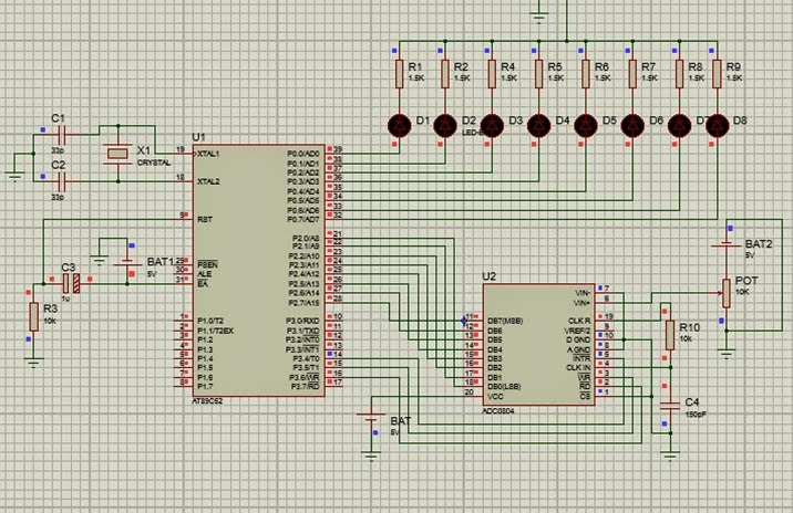
below figure demonstrates the principle and operation of interfacing a simple ADC 0804 using 8051 microcontroller.
(courtesy: Engineergargae.com)


Program:  

#include "REGX52.H" 

#define Mydata P2 
#define LED P0 
#define INTR P1_3 
#define WR P1_1 
#define RD P1_0 

void main() 
 { 
  unsigned char value; 
  Mydata=0xFF; //make P1 as input 
  INTR=1; RD=1; WR=1; 
   while(1) 
    { 
     WR=0; //send WR pulse 
     WR=1; //L to H (start conversion) 
     while(INTR==1); //wait for End of Conversion 
     RD=0; //send RD pulse 
     value=Mydata; //read value 
     LED=value; //display on 8-LEDs 
    } 
  }

Explanation:

There are 3 different values are used INTR(interrupt), RD(read), WR(write). Whereas, Mydata takes the input ADCo8o4 converts the data taken from the microcontroller and converted to digital values in the ouput connected to the LEDs. When WR=1 the conversion takes place until the RD=0  has been sent.

Comments

Popular posts from this blog

Buzzer interface with 8051 microcontroller

Buzzer  is a electronic device that converts the electronic signal into buzzing noise, that is applied to it. It can be used as electronic bell or as quiz buzzer in many applications around us. Here, i world like to discuss the interfacing of a small buzzer with 8051 microcontroller and how different projects can be constructed. Buzzer Interfacing: This project shows the interface with AT89S52 microcontroller to a buzzer. When a push button is pressed, the buzzer will get ON and OFF ( number of times set in the code ) and then stops. Circuit Diagram: - The port P1 of the microcontroller is connected to buzzer. This type of connection is possible, if the current requirements of the buzzer is not more than 20mA. The output is in current source mode so that buzzer will turn ON when the output of the port is logic LOW. Switch is connected to port P3 which remains at logic HIGH by pull up resistor.  Code: #include "REG52.h" #define buz P1 sbit SW=P3^0; long int i; voi

How to Switch OFF Citizen Calculator

You might be confused on seeing no OFF button on your calculator. Actually, these are general calculator available at low cost in the market. They process simple calculations like division, subtraction, Addition, Multiplication. But, how will you OFF that calculator having no option on them. There is always a trick which OFF them. It depends on the company calculator and their series to which they belong. I can tell you about Citizen Calculator CT-500 (as you can see in the image), how can you switch OFF it and can save battery too. If you leave calculator idle for 6-7 minutes, it will goes OFF automatically. My calculator goes OFF in 6.50 minutes from the point of leaving it idle. But, this is not the power saving trick for these types of calculator having not much backup battery. To save the power of your normal calculator, here is the trick to switch OFF it. Press ' /(divide sign)', 'x(multiply sign)', '%(percentage sign)', 'autoreplay option(

Different ways to generate delays in 8051

The delay length in 8051 microcontroller depends on three factors: The crystal frequency the number of clock per machine the C compiler. The original 8051 used 1/12 of the crystal oscillator frequency as one machine cycle. In other words, each machine cycle is equal to 12 clocks period of the crystal frequency connected to X1-X2 pins of 8051. To speed up the 8051, many recent versions of the 8051 have reduced the number of clocks per machine cycle from 12 to four, or even one. The frequency for the timer is always 1/12th the frequency of the crystal attached to the 8051, regardless of the 8051 version. In other words, AT89C51, DS5000, and DS89C4x0 the duration of the time to execute an instruction varies, but they all use 1/12th of the crystal's oscillator frequency for the clock source. 8051 has two different ways to generate time delay using C programming, regardless of 8051 version. The first method is simply using Loop   program function in which Delay() function i