
Test LED emit light or not using Multimeter

Test your LED using Digital Multimeter by simply connecting lead to cathode-anode ends of LED. LED is a type of diode that emits light when external voltage is applied.

Steps to Test LED:
  1. Connect the black lead to the COM terminal on the multimeter.
  2. Connect the red lead to the Ohm terminal, unless your particular model differs.
  3. Turn the dial to the diode symbol on the multimeter. This allows for electric current to travel in one direction (the arrow) and not the other.
  4. Choose a regular red LED.
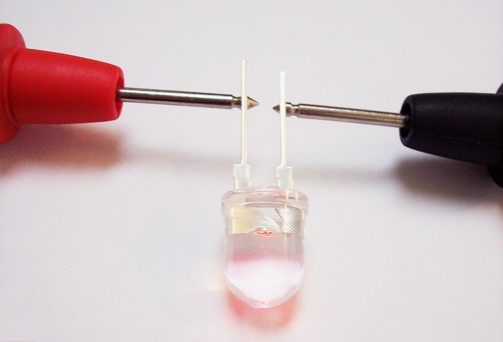
  5. Connect the black probe to the cathode end of the LED, which usually is the shorter end and/or cut flat at its bottom. Connect the red probe to the anode end of the LED.
  6. You will find that LED will light up, showing it is correct to use in your project.
  7. LED will light due to the battery power of multimeter and completing the connection.
LED Forward Voltage Drop The value displayed on your multimeter is called the forward voltage drop. This indicates the quantity of voltage used up by the LED, or dropped, when current is traveling in the appropriate direction, forward. This kind of data is extremely useful when it comes to building your own robot or designing your circuit board. You will definitely need to keep track of the total voltage used by your robot, whether it is from a LED or some other component, in order to choose a battery strong enough to power it. Therefore, it is equally important for you to purchase the LEDs that your battery can sustain. Usually, you should not purchase an LED with a forward voltage exceeding 4V, because most robotic circuits can not function at such voltages.


Comments

Popular posts from this blog

Buzzer interface with 8051 microcontroller

Buzzer  is a electronic device that converts the electronic signal into buzzing noise, that is applied to it. It can be used as electronic bell or as quiz buzzer in many applications around us. Here, i world like to discuss the interfacing of a small buzzer with 8051 microcontroller and how different projects can be constructed. Buzzer Interfacing: This project shows the interface with AT89S52 microcontroller to a buzzer. When a push button is pressed, the buzzer will get ON and OFF ( number of times set in the code ) and then stops. Circuit Diagram: - The port P1 of the microcontroller is connected to buzzer. This type of connection is possible, if the current requirements of the buzzer is not more than 20mA. The output is in current source mode so that buzzer will turn ON when the output of the port is logic LOW. Switch is connected to port P3 which remains at logic HIGH by pull up resistor.  Code: #include "REG52.h" #define buz P1 sbit SW=P3^0; long i...

Different ways to generate delays in 8051

The delay length in 8051 microcontroller depends on three factors: The crystal frequency the number of clock per machine the C compiler. The original 8051 used 1/12 of the crystal oscillator frequency as one machine cycle. In other words, each machine cycle is equal to 12 clocks period of the crystal frequency connected to X1-X2 pins of 8051. To speed up the 8051, many recent versions of the 8051 have reduced the number of clocks per machine cycle from 12 to four, or even one. The frequency for the timer is always 1/12th the frequency of the crystal attached to the 8051, regardless of the 8051 version. In other words, AT89C51, DS5000, and DS89C4x0 the duration of the time to execute an instruction varies, but they all use 1/12th of the crystal's oscillator frequency for the clock source. 8051 has two different ways to generate time delay using C programming, regardless of 8051 version. The first method is simply using Loop   program function in which Delay() funct...

Comparison Chart Between 8051, 8052, 8031and 8751

8051 is a popular 8-bit microcontroller and has been used in many applications since Intel introduced it. Many 8051 architecture are produced by Triscend, Intel, Atmel, Philips, Infineon (Siemens), ISSI, and Max Corp. Today, 8051 microcontrollers may not be popular but, the 8051 architecture is still popular and employed in thousands of embedded applications. This 8-bit architecture has been different segments such as 8052, 8051, 8751 and 8031 . 8052 is the super-set of 8051 and 8031 is the memory-less microcontroller hence, it has interfaced with external ROM. Whereas, 8751 chip has only 4Kbytes of on chip UV-EPROM. Everyone knows about the general 40-pin microcontroller i.e. 8051 introduced by Intel in 1980s and consists of serial communication pins, Timer, Interrupts, RAM, ROM. It has 4 ports and each port has 8 pins, total 32 pins and other 8 pins for other purposes. 8052 is the super-set of 8051 that consists of 8K bytes of internal RAM (4K in 8051), 256 by...