What is 7 Segment Display?
 7 Segment Display is an array of 8 LEDs connected or arranged in a special pattern together to form or display the digits from 0-9 and Dot functions also. The 7-segments are arranged as a rectangle of two vertical segments on each side with one horizontal segment on the top, middle, and bottom. Additionally, the seventh segment bisects the rectangle horizontally. There are also fourteen-segment displays and sixteen-segment displays.
It is composed of 7 LEDs assigning specific alphabet to each and 1 LED acts as a dot in the display. Every LED is assigned a name from 'a' to 'h' and is identified by its name. Seven LEDs 'a' to 'g' are used to display the numerals while eighth LED 'h' is used to display the dot/decimal.
Concept:
A 7-segment is generally available in ten pin package. While eight pins correspond to the eight LEDs, the remaining two pins (at middle) are common and internally shorted. These segments come in two configurations, namely, Common cathode (CC) and Common anode (CA). In CC configuration, the negative terminals of all LEDs are connected to the common pins. The common is connected to ground and a particular LED glows when its corresponding pin is given high. In CA arrangement, the common pin is given a high logic and the LED pins are given low to display a number.


This below table specify how 7-segment will display the digit when one of the LED is OFF or ON accordingly.

Interfacing with 8051
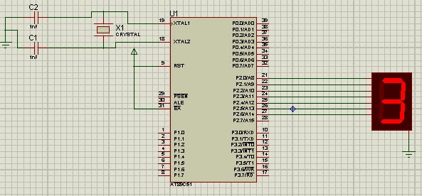
The circuit diagram shown above is of an AT89S51 microcontroller based 0 to 9 counter which has a 7 segment LED display interfaced to it in order to display the count. This simple circuit illustrates two things. How to setup simple 0 to 9 up counter using 8051 and more importantly how to interface a seven segment LED display to 8051 in order to display a particular result. The common cathode seven segment display D1 is connected to the Port 1 of the microcontroller (AT89S51) as shown in the circuit diagram. R3 to R10 are current limiting resistors. S3 is the reset switch and R2,C3 forms a debouncing circuitry. C1, C2 and X1 are related to the clock circuit. The software part of the project has to do the following tasks.

#define seg_data P2
intnum=0;
void display_digit(int);
void delay(int);
void main()
{
while(1)
{
for(num=0;num<10 br="" num=""> {
display_digit(num);
delay(20000);
}
}
}
void delay(int x)
{
int i;
for(i=0;i}
voiddisplay_digit(int digit)
{
switch(digit)
{
case 0:
seg_data=0x3f;
break;
case 1:
seg_data=0x06;
break;
case 2:
seg_data=0x5b;
break;
case 3:
seg_data=0x4f;
break;
case 4:
seg_data=0x66;
break;
case 5:
seg_data=0x6d;
break;
case 6:
seg_data=0x7d;
break;
case 7:
seg_data=0x07;
break;
case 8:
seg_data=0x7f;
break;
case 9:
seg_data=0x6f;
break;
}
}
 7 Segment Display is an array of 8 LEDs connected or arranged in a special pattern together to form or display the digits from 0-9 and Dot functions also. The 7-segments are arranged as a rectangle of two vertical segments on each side with one horizontal segment on the top, middle, and bottom. Additionally, the seventh segment bisects the rectangle horizontally. There are also fourteen-segment displays and sixteen-segment displays.
It is composed of 7 LEDs assigning specific alphabet to each and 1 LED acts as a dot in the display. Every LED is assigned a name from 'a' to 'h' and is identified by its name. Seven LEDs 'a' to 'g' are used to display the numerals while eighth LED 'h' is used to display the dot/decimal.
Concept:
A 7-segment is generally available in ten pin package. While eight pins correspond to the eight LEDs, the remaining two pins (at middle) are common and internally shorted. These segments come in two configurations, namely, Common cathode (CC) and Common anode (CA). In CC configuration, the negative terminals of all LEDs are connected to the common pins. The common is connected to ground and a particular LED glows when its corresponding pin is given high. In CA arrangement, the common pin is given a high logic and the LED pins are given low to display a number.
Common Cathode and Common Anode Configuration
Configuration:
This below table specify how 7-segment will display the digit when one of the LED is OFF or ON accordingly.
Packaging of 7-Segment Display:
Seven-segment displays can be packaged in a number of ways. Three typical packages are shown above.
1. On the left we see three small digits in a single 12-pin DIP package. The individual digits are very small, so a clear plastic bubble is molded over each digit to act as a magnifying lens.
The sides of the end bubbles are flattened so that additional packages of this type can be placed end-to-end to create a display of as many digits as may be needed.
2. The second package is essentially a 14-pin DIP designed to be installed vertically.
Note that for this particular device, the decimal point is on the left. This is not true of all seven-segment displays in this type of package.
One limitation of the DIP package is that it cannot support larger digits. To get larger displays for easy reading at a distance, it is necessary to change the package size and shape.
3. The package on the right above is larger than the other two, and thus can display a digit that is significantly larger than will fit on a standard DIP footprint. Even larger displays are also available; some digital clocks sport digits that are two to five inches tall.
Interfacing with 8051
The circuit diagram shown above is of an AT89S51 microcontroller based 0 to 9 counter which has a 7 segment LED display interfaced to it in order to display the count. This simple circuit illustrates two things. How to setup simple 0 to 9 up counter using 8051 and more importantly how to interface a seven segment LED display to 8051 in order to display a particular result. The common cathode seven segment display D1 is connected to the Port 1 of the microcontroller (AT89S51) as shown in the circuit diagram. R3 to R10 are current limiting resistors. S3 is the reset switch and R2,C3 forms a debouncing circuitry. C1, C2 and X1 are related to the clock circuit. The software part of the project has to do the following tasks.
- Form a 0 to 9 counter with a predetermined delay (around 1/2 second here).
- Convert the current count into digit drive pattern.
- Put the current digit drive pattern into a port for displaying.
Code
#include"REGx52.h"#define seg_data P2
intnum=0;
void display_digit(int);
void delay(int);
void main()
{
while(1)
{
for(num=0;num<10 br="" num=""> {
display_digit(num);
delay(20000);
}
}
}
void delay(int x)
{
int i;
for(i=0;i
voiddisplay_digit(int digit)
{
switch(digit)
{
case 0:
seg_data=0x3f;
break;
case 1:
seg_data=0x06;
break;
case 2:
seg_data=0x5b;
break;
case 3:
seg_data=0x4f;
break;
case 4:
seg_data=0x66;
break;
case 5:
seg_data=0x6d;
break;
case 6:
seg_data=0x7d;
break;
case 7:
seg_data=0x07;
break;
case 8:
seg_data=0x7f;
break;
case 9:
seg_data=0x6f;
break;
}
}
Explanation of Code:
- This code implements single seven segment LED display with common cathode to 8051 microcontroller. Connect common cathode pin to any port pin of microcontroller as we define it C1 in code. Now, ON/OFF that pin to view the character on display. Mark the values accordingly to extract the HEX value and pass it to the port to seven segment to display character
bhoto chamaro...ata jata kuch nhi...galat program likh k output lane walo..janta maaf nahi kregi!!
ReplyDeleteIts time to move to flexible segment display
ReplyDelete