7-Segment LED
display is the combination of 8 LEDs in a special digital display
format. I have explained the 7-segement LED displays in earlier post and
simple digit display on it. Now, i want to discuss the interfacing of
different 7-segment displays with 8051 microcontroller.
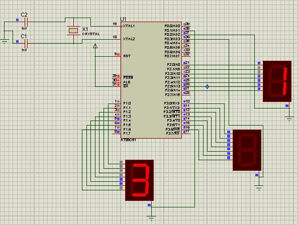
- As you can see above circuit diagram in which three 7-segments are connected to port P1, P2, P3 and the common cathode are connected to the port P0.1, P0.2 and P0.3. Now, we have to run a counter from 0-999. So, the basic concept is that you implement binary to hexadecimal conversion code in which MSB and LSB are extracted. Now, take MSB as hundredth digit and LSB as ones place digit.
Now, write hexa value for each character. Example, when '1' is called from main program it goes to switch() case where it picks up the hexa value to switch ON that particular LEDs in order to display numeric '1'. Now, implement the other characters in similar way.
Interfacing:
- As you can see above circuit diagram in which three 7-segments are connected to port P1, P2, P3 and the common cathode are connected to the port P0.1, P0.2 and P0.3. Now, we have to run a counter from 0-999. So, the basic concept is that you implement binary to hexadecimal conversion code in which MSB and LSB are extracted. Now, take MSB as hundredth digit and LSB as ones place digit.
Code:
#include"REGx52.h"
#define seg_data P1
#define seg_data1 P2
#define seg_data2 P3
sbit seg1=P0^1;
sbit seg2=P0^2;
sbit seg3=P0^3;
int num=0;
int ones=0,tens=0,hundreds=0;
void display_digit(int );
void delay();
void display_digit1(int );
void display_digit2(int );

void main()
{
while(num<=999)
{
ones=num%10;
tens=(num/10)%10;
hundreds=(num/100);
seg1=seg2=seg3=1;

display_digit(ones);
seg1=0;
delay();
seg1=1;

display_digit1(tens);
seg2=0;
delay();
seg2=1;

display_digit2(hundreds);
seg3=0;
delay();
seg3=1;
num++;
}
}
void delay()
{
long int k;
for(k=0;k<10000;k++};
}
void display_digit(int a)
{
switch(a)
{
case 0:
seg_data=0x00;
break;

case 1:
seg_data=0x06;
break;

case 2:
seg_data=0x5b;
break;

case 3:
seg_data=0x4f;
break;

case 4:
seg_data=0x66;
break;

case 5:
seg_data=0x6d;
break;

case 6:
seg_data=0x7d;
break;

case 7:
seg_data=0x07;
break;

case 8:
seg_data=0x7f;
break;

case 9:
seg_data=0x6f;
break;
}
}

// for tens place

void display_digit1(int b)
{
switch(b)
{
case 0:
seg_data1=0x00;
break;

case 1:
seg_data1=0x06;
break;

case 2:
seg_data1=0x5b;
break;

case 3:
seg_data1=0x4f;
break;

case 4:
seg_data1=0x66;
break;

case 5:
seg_data1=0x6d;
break;

case 6:
seg_data1=0x7d;
break;

case 7:
seg_data1=0x07;
break;

case 8:
seg_data1=0x7f;
break;

case 9:
seg_data1=0x6f;
break;
}
}

//for hundredth place

void display_digit2(int c)
{
switch(c)
{

case 0:
seg_data2=0x00;
break;

case 1:
seg_data2=0x06;
break;

case 2:
seg_data2=0x5b;
break;

case 3:
seg_data2=0x4f;
break;

case 4:
seg_data2=0x66;
break;

case 5:
seg_data2=0x6d;
break;

case 6:
seg_data2=0x7d;
break;

case 7:
seg_data2=0x07;
break;

case 8:
seg_data2=0x7f;
break;

case 9:
seg_data2=0x6f;
break;
}
}
Explanation of code:
- In code, we implemented the different function for different display so that individual counter can be run. But, when ones place digit number reaches to 9 from 0, the tens place digit gets incremented automatically and so on. For this, create a while() loop to 999 and implement.Now, write hexa value for each character. Example, when '1' is called from main program it goes to switch() case where it picks up the hexa value to switch ON that particular LEDs in order to display numeric '1'. Now, implement the other characters in similar way.
How can an 8051 port with a pull up resistor of 100K possibly source the necessary current to light up an LED. The LEDs need to be common anode, with segement resistors, so the 8051 can pull down a segment (because the port can sink up to 15ma but source very little)
ReplyDeleteIt is indeed a challenge for an 8051 microcontroller with a pull-up resistor of 100K to directly source enough current to light up an LED, especially if the LEDs require higher current levels than what the microcontroller can provide when sourcing current. The 8051 is generally not designed to handle high-current outputs when sourcing.
ReplyDeleteTo overcome this limitation and still drive the LEDs effectively, you can use a technique called "charlieplexing." Charlieplexing is a method that allows you to control multiple LEDs using fewer pins than traditional methods.
Here's how you can do it:
Common Anode LEDs: Since you mentioned that the LEDs are common anode, this means that the anodes of all the LEDs are connected together.
Segment Resistors: Each LED segment requires a current-limiting resistor when connecting to the microcontroller's pins. Make sure you use appropriate resistors to limit the current through each segment.
Charlieplexing Principle: Charlieplexing works on the principle of selectively enabling specific LED segments by manipulating the state of the microcontroller pins. You can switch between driving a segment as an anode (HIGH) or sinking current as a cathode (LOW).
Pins Combination Formula: To determine the number of LEDs you can control, use the formula n*(n-1), where n is the number of available microcontroller pins. This formula calculates the number of unique pin combinations possible.
For example, if you have three microcontroller pins (P1, P2, P3), you can control six LEDs (3*(3-1)) using charlieplexing.
Dynamic Control: To light up a particular LED segment, you need to dynamically set the microcontroller pins as either OUTPUT and HIGH or OUTPUT and LOW based on the LED you want to activate. The others should be set as INPUT.
Timing Considerations: You need to take care of timing when switching between states to avoid creating a short circuit. Proper software implementation is crucial for successful charlieplexing.
Charlieplexing can be a bit tricky to implement, especially if you have many LEDs to control, but it offers a way to overcome the limited sourcing capabilities of the 8051 microcontroller. Always ensure to calculate the appropriate current-limiting resistors for each segment to protect the microcontroller and the LEDs from excess current.
As a final note, if you find charlieplexing too complex or if you need to control a significant number of LEDs, you can use external driver ICs, such as shift registers or LED driver chips, to simplify the circuit and handle the current requirements effectively.